
Technical & installation
The details behind the woodgrain.
Standards, downloads, profile drawings and installation guidance for specifiers, builders, installers and inspectors.
Downloads
Documents
Always confirm you are using the most current version. Product specifications are subject to change without notice.
Product certifications
Standards & testing
- CGSB 93.1Aluminum siding and soffit-related product requirements
- CGSB 93.2Extruded aluminum siding and cladding
- CAN/ULC-S135Combustibility parameters of building materials (oxygen consumption calorimeter)
- CAN/ULC-S102Surface burning characteristics of building materials and assemblies
- ASTM D4214Coating performance: no chalking after 2,000 hours
- Impact / hailExceeds standard aluminum siding
Material: Powder-coated 6063-T5 extruded aluminum.
Profiles
Two reveals.
One concealed system.
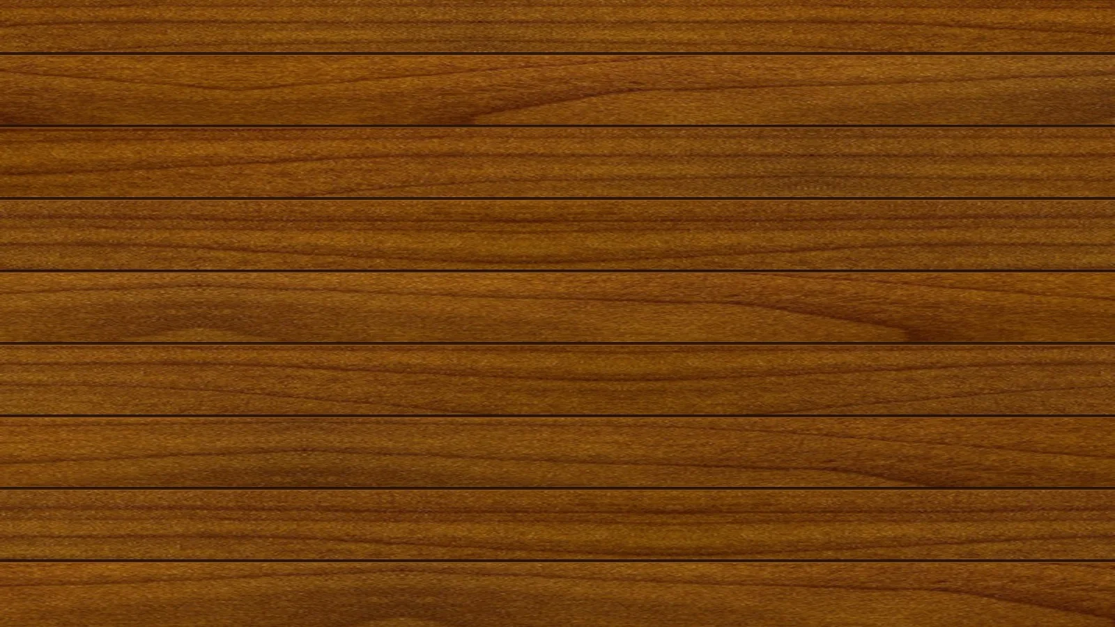 AFX-TG44″ nominal reveal · board rhythm, not to scale
AFX Element Line
Element 4″ panel
Tongue-and-groove cladding and soffit panel with a 4″ nominal reveal, installed on the concealed Floating Quick Clip system and finished with matching trims.
- Product code
- AFX-TG4
- Reveal
- 4″ nominal
- Length
- 16 ft · 4.88 m
- Fastening
- Floating Quick Clip
- Uses
- Siding · soffit · cladding
- Finishes
- 5 woodgrains
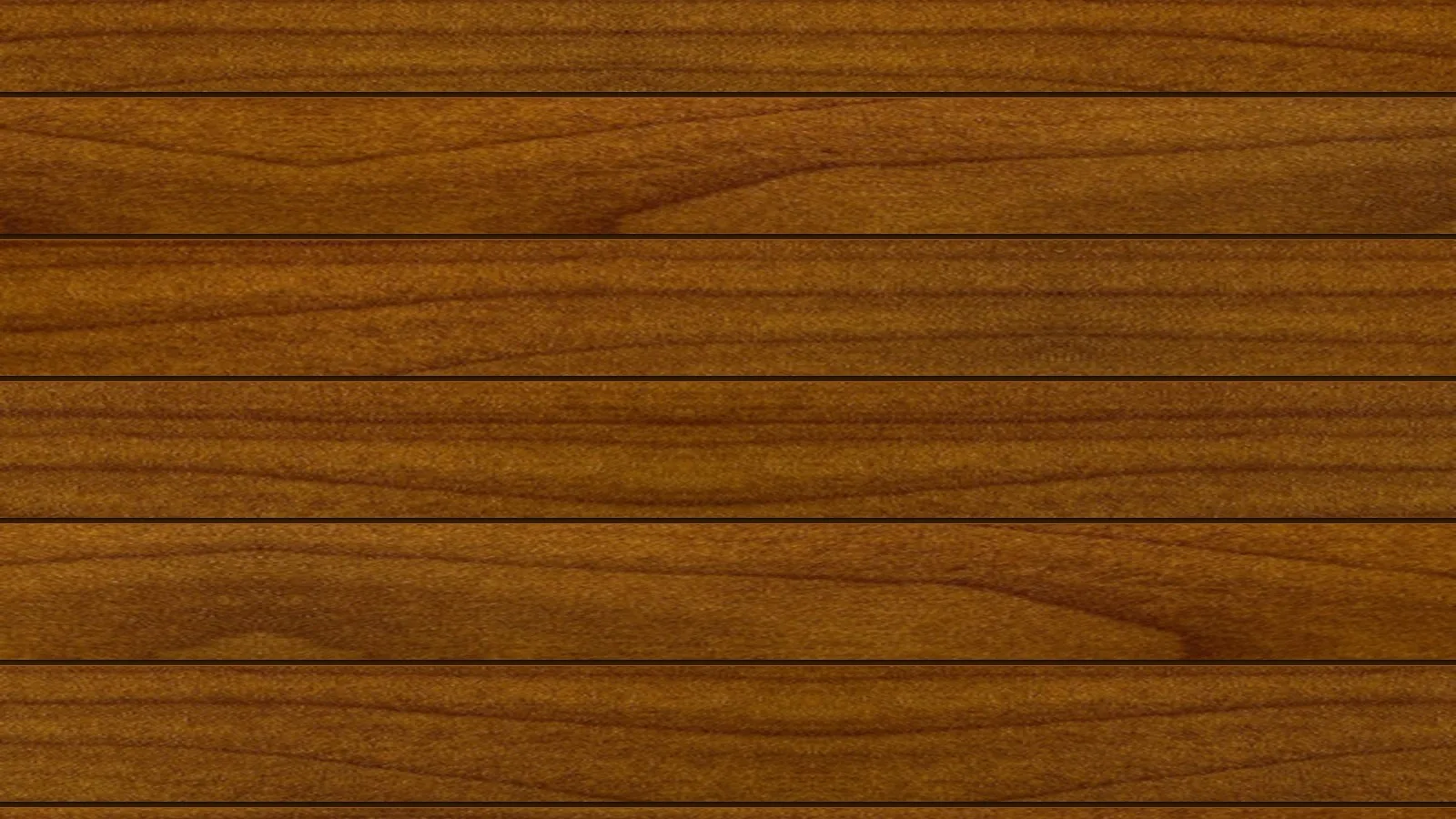 AFX-TG66″ nominal reveal · board rhythm, not to scale
AFX Element Line
Element 6″ panel
Tongue-and-groove cladding and soffit panel with a 6″ nominal reveal, installed on the concealed Floating Quick Clip system and finished with matching trims.
- Product code
- AFX-TG6
- Reveal
- 6″ nominal
- Length
- 16 ft · 4.88 m
- Fastening
- Floating Quick Clip
- Uses
- Siding · soffit · cladding
- Finishes
- 5 woodgrains
Installation at a glance
Built for a clean, efficient install.
A summary of the installation guide. We strongly recommend installation by experienced professionals, and all parties should review the full guide before starting work.
- 01SSS-003 · SSC-014
Starter strip & Floating Quick Clips
TrueLine starter strip at the lowest point of the finished wall, fastened through the flange at every second clip.
- 02TCA-009 · TCB-016
DuoFit corner bases
Install all corner bases before panels. The same two extrusions form inside and outside corners.
- 03TJA-009
J-trim, where required
Vertical termination where a panel run does not end at a corner.
- 04TFA-014
Twin cap trim base
Finishing base between corner bases and J-trim, aligned with adjacent vertical trims.
- 05AFX-TG4 · TG6
Element panels
Install bottom-to-top, engaging each tongue-and-groove joint over the concealed clips.
- 06TFB-014
Corner & trim caps
Cut caps to height and snap onto the installed bases. Non-structural, they allow for linear expansion.
Plan the layout
- Confirm layout, alignment, terminations and expansion breaks before installation.
- Substrates must be straight, true, dry and free of debris.
- Do not install directly over pressure-treated substrates without an approved protective barrier.
Fastening
- Minimum two Floating Quick Clips (SSC-014) per panel.
- Clip spacing: 32″ on centre for normal wind loads, 16″ for high-wind conditions.
- #10 pan-head stainless steel, or otherwise exterior-rated, fasteners.
- Consult the authority having jurisdiction or project engineer for project-specific requirements.
Expansion
- Leave a ¼″ gap at both panel ends where concealed by trim.
- Runs of 0–16 ft: ¼″ gap. Runs of 16–32 ft: ½″ gap.
- Over 32 ft, use J-trim to create expansion breaks.
- Leave ⅛″ between adjoining vertical trim components.
Cutting & handling
- Compound mitre saw or table saw with a 60–80T carbide blade for non-ferrous metal.
- Wear hearing and eye protection. Secure material and remove sharp edges after cutting.
- Handle with care to protect the coating from scratches.
- Tap tongue-and-groove joints together with a rubber mallet for full engagement.
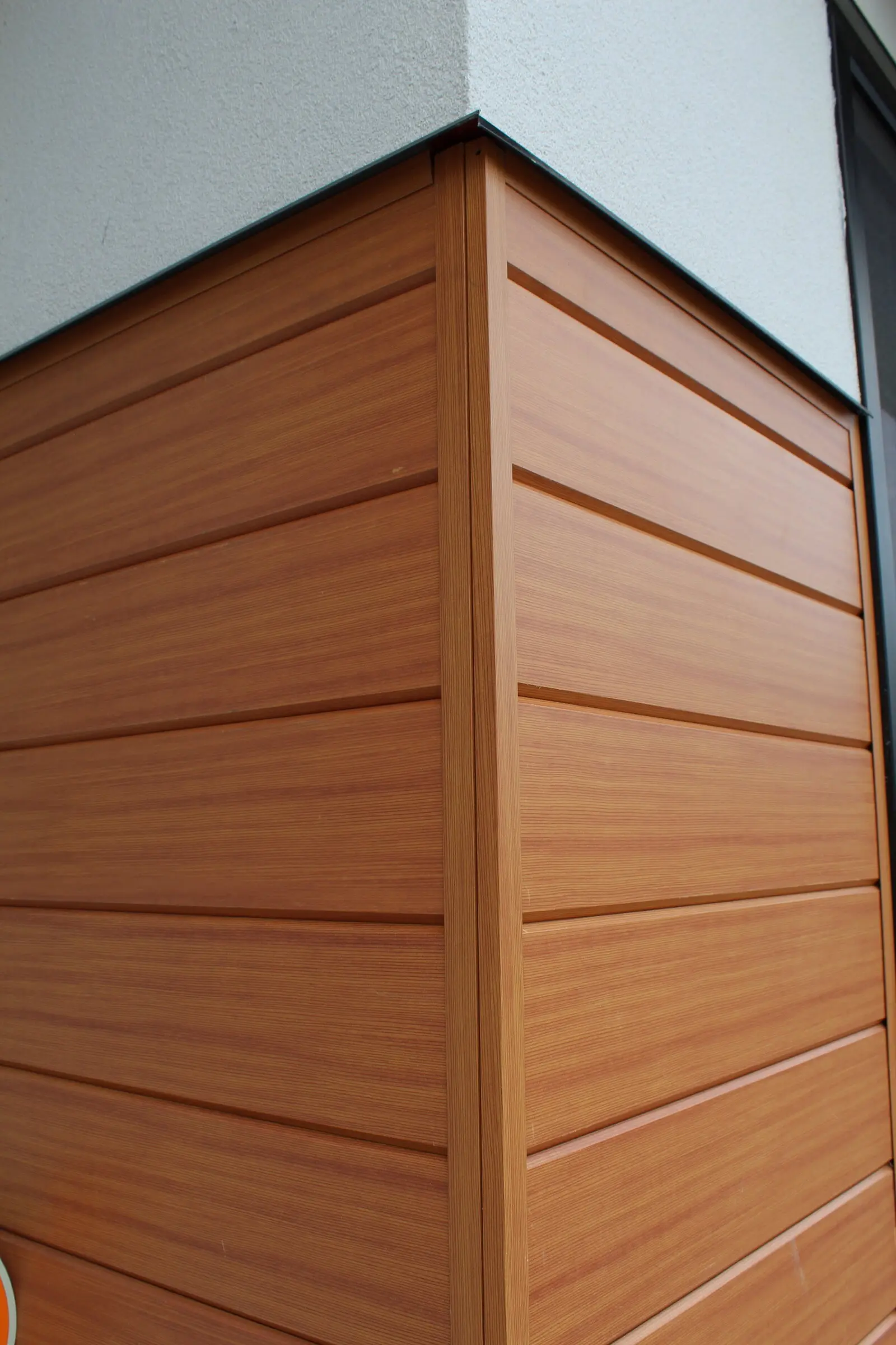
Care & cleaning
Mild detergent, water, soft brush. That’s it.
Never use abrasive or aggressive cleaners on AFX products. No staining, sealing or repainting required.
This summary is for general information only. Installation methods may vary with building design, environmental conditions and applicable building codes. The installer, contractor, architect or project engineer is responsible for ensuring compliance with local codes, regulations and project specifications. Refer to the full installation guide for details.
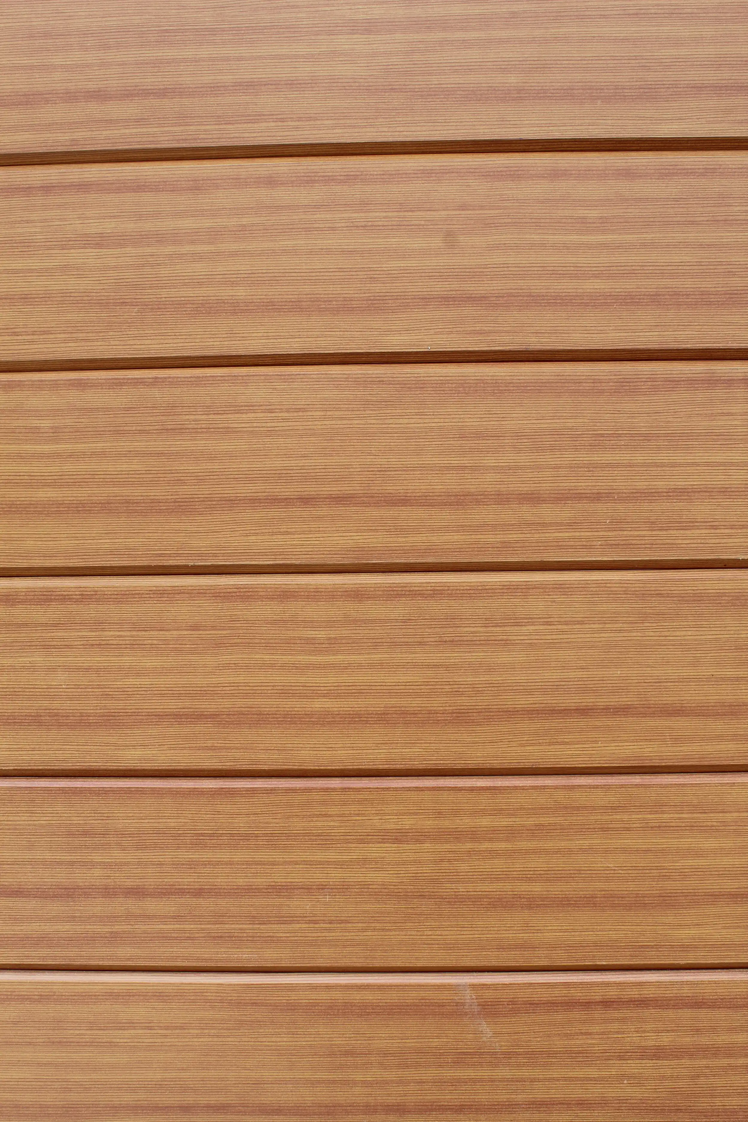
Quote & samples
Need drawings or project support?
Ask for project drawings, a project-specific quote or help on site. Local assistance is available in Kelowna, BC.